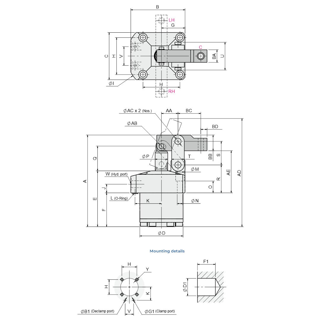
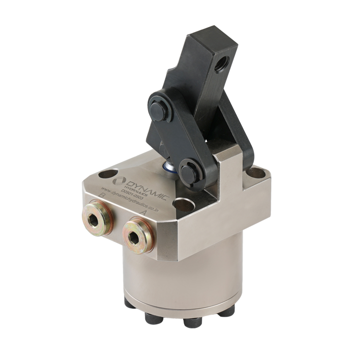
Quick inquiry
Link clamp
Information

The Link clamp is designed with sufficient unclamp angle and

compact size so that there is no interference when loading and unloading

the workpiece takes place, maximizing designer convenience.


  • Hardened and chromed alloy steel piston rods run longer with less wear
  • Wiper seals reduce contamination of dust for the long run of the Link clamp
  • Special coating on the cylinder body helps prevent Rusting and scratching


Specifications
  • Minimum operating pressure: 10 Bar
  • Maximum operating pressure: 70 Bar
  • Operating temperature: 10 - 70 °C


Share this product

Ordering Method: Product Code - DL

Link clamp


All dimensions are in mm except otherwise specified.

Model No. Piston (Bore)Ø A B C ØD (e8) E F G H ØI J K L (O Ring) ØM ØN O ØP Q R S T U V W (Hyd. Port) Y AA ØAB ØAC AD AE BA BB BC BD Lock Cyl.Area (cm²) Full Stroke (mm) Locking Stroke (mm) Extra Stroke (mm) Cyl. Vol. (cm3) Clamp Cyl. Vol. (cm3) Declamp Clamping force at 70 Bar (Kg.) Design Pressure (Bar) Operating Temp. (°C) Weight (Kg.) ØB1, ØG1 ØD1 (E8) F1 ± 0.2
DL - 040 25 90.5 54 45 40 57.5 32.5 22.5 34 73 11 26 4 x 2 9.5 5.5 15 12 24.5 30 22 12 25 18 G1/8" M5 16 5 6 106.3 44 12 14 20 6.5 4.9 20 16 4 8.3 6.4 265 105 10 - 70 0.72 1.5 40 34.5
DL - 048 30 105 61 51 48 66 38 25.5 40 83 11 30 4 x 2 9.5 5.5 17.5 14 29 34.5 26 13 28 22 G1/8" M5 18.5 6 6 122.6 51 12 16 23.5 6 7.07 23.5 19.5 4 14.5 11.3 349 105 10 - 70 1.07 1.5 48 40
DL - 055 35 116.5 69 60 55 71 43 30 47 88 11 33.6 4 x 2 11 6.8 15 16 31.5 35.5 30 16 35.5 24 G1/8" M6 21 6 8 137.1 53.5 16 20 29 8 9.62 26 23 3 22.1 17.5 465 105 10 - 70 1.56 1.5 55 45
DL - 065 45 136 81 70 65 80.5 50.5 35 55 106 11 39.5 6 x 2 11 6.8 15.5 18 38.5 39 35.5 19 43.5 30 G1/4" M6 24.5 8 10 159.4 60.5 19 25 32.5 10 15.9 29.5 26 3.5 42.1 35.4 842 105 10- 70 2.44 1.5 65 52.5
DL - 075 55 157 94.5 85 75 90 53 42.5 63 120 12 45 6 x 2 14 9 19.5 22 45 48 43.5 25 48 32 G1/4" M8 30 10 12 182.8 72 22 32 38 11 23.7 35 31 4 75.8 63.9 1264 105 10 - 70 3.8 1.5 75 55
DL - 090 65 185 111 100 90 106 66 50 75 136 12 52.5 6 x 2 17.5 11 19 28 52.5 52.5 53 28 57.5 37 G1/4" M10 36 12 15 213.7 81.5 25 38 41.5 14 33.16 39 36 3 118.5 96.5 1985 105 10 - 70 6.3 3 90 68
DL - 105 75 217 127 120 105 123 73 60 88 154 15 60 6 x 2 20 14 24.5 36 62 64 64 32 71 45 G3/8" M12 44 15 18 252 99 32 45 51 17 44.5 49 45.5 3.5 199.67 153.66 2566 105 10 - 70 10.3 4 105 75
Note:

Actual force may vary by 10% - 15% due to friction loss. Make sure the clamp mountingflange and lever are parrallel to the clamping surface.

The lever contact surface should be within ± 2 degree parrallel to the body mounting flange face or 90 degree to the mounting flange face when clamping a workpiece.

Warning:

Operating above 70 Bar may damage the Link clamp and will void the warranty.

Link clamp - Lever


All dimensions are in mm except otherwise specified.

Model No. a b c d e f g h i j k Øl Øm n o p
DL - 040 48 12 14 6 15 12 13 3 5.5 16 20 5 6 5.5 2.5 M6
DL - 048 54 12 16 6 16 14 13 3 6 18.5 23.5 6 6 6 3.5 M6
DL - 055 64 16 20 8 17 15 17 4 6 21 29 6 8 6 6 M8
DL - 065 75 19 25 10 22 21 22.5 5 8 24.5 32.5 8 10 8 6 M10
DL - 075 89 22 32 11 26 24 25 5 10 30 38 10 12 10 9.5 M12
DL - 090 102.5 25 38 13 31 28 25 6 11 36 41.5 12 15 11 13 M12
DL - 105 125 32 45 16 38 35 36 6 13 44 51 15 18 13 16 M16


All dimensions are in mm except otherwise specified.

Note:

Actual force may vary by 10% - 15% due to friction loss. Make sure the clamp mountingflange and lever are parrallel to the clamping surface.

The lever contact surface should be within ± 2 degree parrallel to the body mounting flange face or 90 degree to the mounting flange face when clamping a workpiece.

Warning:

Operating above 70 Bar may damage the Link clamp and will void the warranty.