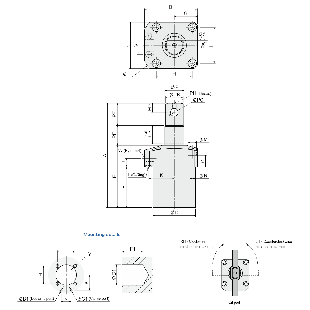
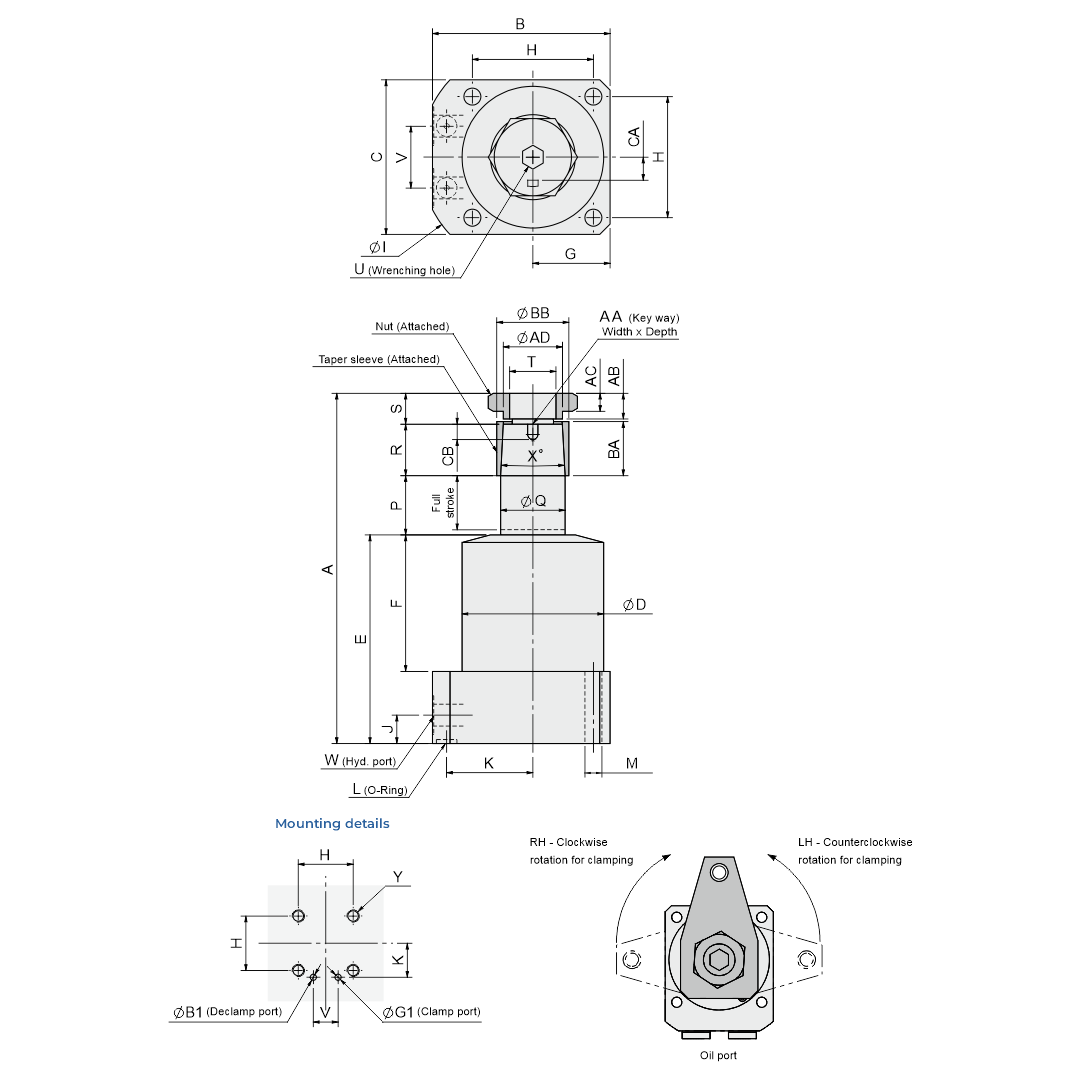
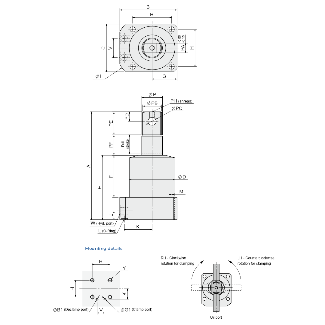
Swing clamp
Dynamic Hydraulics is a reliable Manufacturer and Supplier of Swing Clamp Cylinders in India, offering high-quality hydraulic swing clamps designed for precision, durability, and consistent industrial performance.
Information
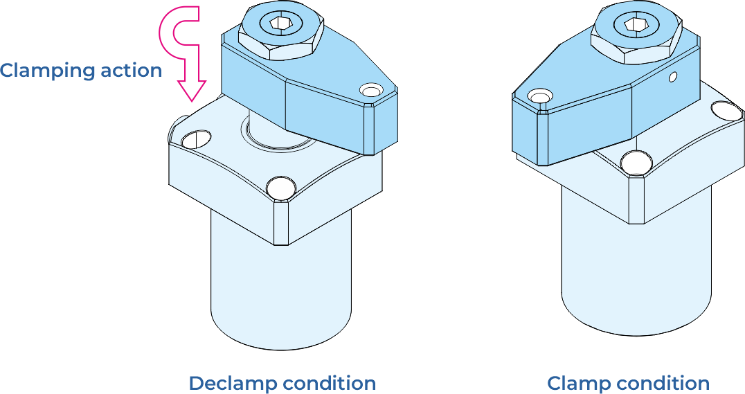
A Swing Clamp Cylinder is a hydraulic clamping device that rotates 90° (clockwise or counter-clockwise) over the workpiece and then applies a strong vertical clamping force. This ensures:
- Secure workpiece holding
- High machining accuracy
- Quick setup and operation
Swing clamp cylinders are essential in industries where fast, repeatable, and precise clamping is required.
Features of swing clamp cylinders
- Heavy-duty construction for long service life
- Hardened and chrome-plated piston rods to minimize wear
- High-quality wiper seals for dust protection and smooth operation
- Corrosion-protected body for improved durability
- Efficient performance at 15–70 bar operating pressure
- Suitable for working temperatures from 10°C to 70°C
Applications
- Our hydraulic swing clamp cylinders are widely used in:
- CNC machining and milling operations
- Drilling and automated production lines
- Assembly fixtures and jigs
- Precision manufacturing requiring fast and secure clamping